
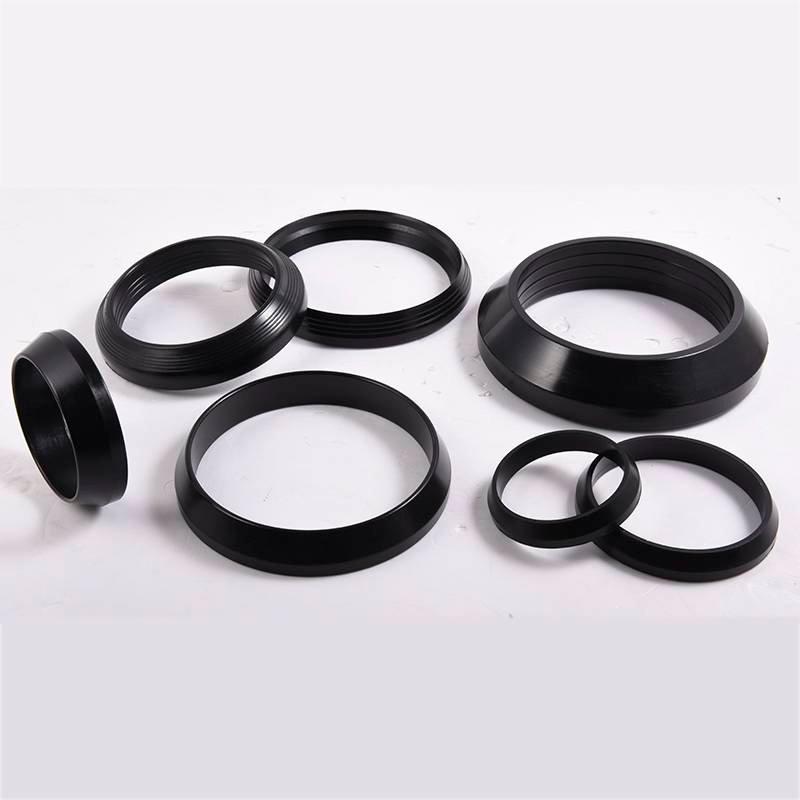
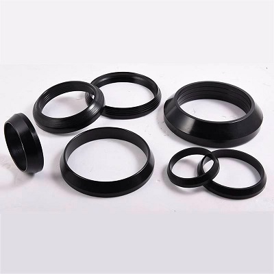
Flange adapter Rubber ring
- Brand:RSL
- Model:DN50-DN2000
- Minimum:50pcs
- Material:EPDM/SBR/NBR
- Payment:L/C or T/T
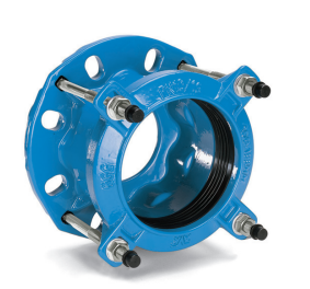
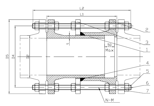
Flange adapter Rubber ring is a seal applied to the flange adapter and pipe connection.
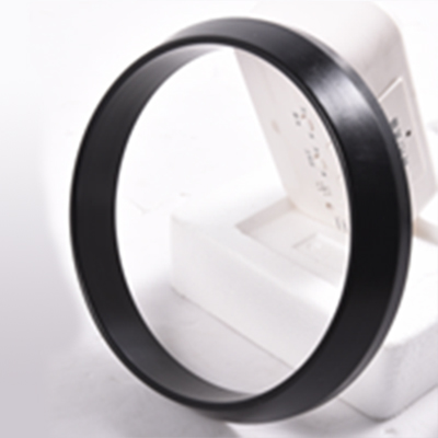
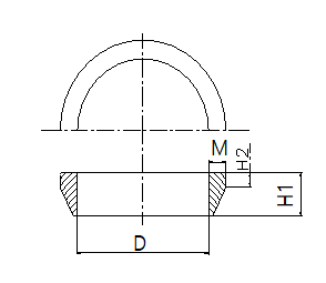
The front end of the rubber ring to form a certain angle, the profile looks like a right triangle. As shown below:
Application
This product is used for the flange adapter, the installation of the inner diameter of the need to close the pipe wall, together with the flange into the adapter slot, rely on tightening screws, the role of pressure on the apron, has reached the effect of sealing leakage.
Taking into account the use of flange adapter requirements, the flange rubber ring physical mechanics requirements, health applications are more stringent requirements.
RSL flange adapter rubber ring has passed the professional standard BS EN681-1 physical performance test, and the EU recognized WRAS certification. Choose our apron, will be able to meet your critical requirements. Come today to contact us!
Flange adapter Rubber ring
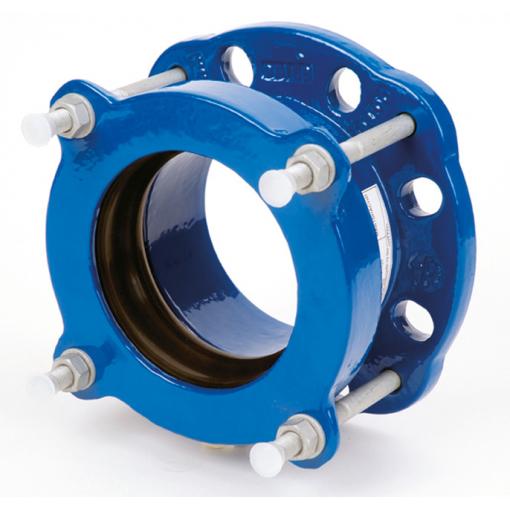
What Is a Flange Adapter?
Flange adapters are an extensive family of flange joint accessories that allow the execution of joints between dissimilar flange types or flanged and non-flanged equipment. The significant flexibility gained by using these devices becomes apparent when the enormous range of common flange types in general use is considered. In fact, most manufacturers of flanges or flanged equipment produce their own lines of flange adapter accessories, allowing their products to be integrated into other systems with ease. Although these adapters are themselves represented by a vast array of different types, they fall into two main categories. The first are flange-to-flange types, with the second being those used to join flanged and non-flanged equipment.
Flanges are little more than flat discs or shoulders integral to or loose fitting on the relevant part or pipe. The flange disc is fitted with a number of holes around its periphery through which locking bolts are passed. To join two similarly flanged pieces of equipment, the two halves are brought together, locking bolts are passed through the holes in both flange discs and tensioned. This pulls the two flanges hard up against one another, effectively joining the two pieces of equipment.
The flange adapter is used where the two pieces of equipment do not have similar flange types or only one-half is flanged. These adapters fall into two broad categories, namely those used on dissimilar flange pairs and those used in situations where a non-flanged part is joined to a flanged part. Flange-to-flange adapters are usually represented by those adapters designed for dissimilarly-sized flanges and those used to join flanges of the same size with differing hole arrangements.
Joints featuring flanges of different sizes may easily be made using a flange adapter featuring one of each of the two flange sizes joined by a short reducer section. These adapters are simply arranged so the relevant flange sizes are matched between the parts and the adapter, and tensioned in the normal fashion. Adapters used to join flanges with differing hole patterns are even simpler and typically consist of a single disc drill halfway through on either side with the two different hole patterns. The holes in the adapter are tapped with a standard screw thread so that, when slipped between the two dissimilar flanges, bolts can be used to tension each of them up against the adapter. In general, this type of adapter will be supplied with a set of the correct bolts.
Flanged to non-flanged joints require a special type of flange adapter that generally has a flange on one end and a secondary locking mechanism suitable for the relevant equipment on the other. For instance, a flange adapter designed to join an non-flanged hose to a flange-equipped pipe will have a suitably-sized flange on one end and a compression or half-shell hose clamp on the other. The flanged end is bolted to the secondary device's flange in the normal way and the non-flanged hose securely attached with the hose clamp.
Flange adapters are used to join a flanged part to the spigot end of a pipe or tube. They are used to connect networks composed of different materials. They can also be specially designed for one material. In this case, they are offered in anchoring or non-anchoring versions. With the self-anchoring (locking) products, concrete anchor blocks are unnecessary.
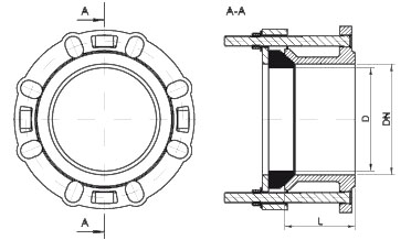
The flange adaptor is the most basic type of dismantling joint. On one side, it has a flange connection in accordance with the required flange standard, on the other an insertion socket for the pipe. A variety of standard pipe types can be connected.
flange adaptors are available for a variety of pipe types. The anti-torque bolts also make the flange adaptor suitable for a fast “one-man installation”.
There are two types of Flange Adapters
1) Weldable Type Flange Adapter
2) Flange Type Flange Adapter
Features:
• ±4° angular deflection
• Drinking water approved EPDM gasket
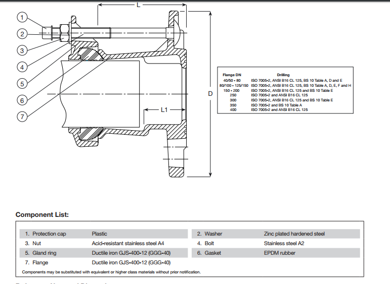
• The design with external bolts prevents corrosion between sleeve and bolts
• The bolts of stainless steel A2 and the nuts of acid-resistant stainless steel A4 are anti-friction coated to offer
easy tightening and to prevent galling
• The bolt ends are protected with plastic caps
• The moulded ribs in the gasket absorb minor imperfections in the pipe
• Ductile iron with epoxy coating according to DIN 30677-2 and AVK guidelines
Installation
1) All of the series 600 mechanical fittings are supplied as an assembled unit ready for use, dismantling of the parts is
unnecessary.
2) Examine fitting before assembling to ensure that no damage has occurred during transit.
3) Check that the sealing range indicated on the label of the fitting is compatible with the actual pipe diameter.
4) When assembling Supa Flange Adaptors, check that the Nom Flange size and Pressure ratings are compatible with the valve.
5) Check that the sealing element supplied is suitable for the medium conveyed in the main.
6) Examine the pipe end to which the fitting is to be assembled, ensuring that it is round and square and free from dents, bulges
and score marks.
7) When assembling to a steel pipe which has longitudinal seam welds, the weld seam must be removed by grinding. Care
should be taken to ensure that the pipe surface profile is maintained.
8) The pipe end must be cleaned by wire brushing, to remove all rust, scale or debris.
9) Lubricate inside diameter of sealing elements with a WRAS approved lubricant.
10) Position pipe end to be coupled, checking that it is level and concentric with the bore of the mating flange, and that the
correct setting gap is maintained.
11) RECOMMENDED GAP SETTINGS
DN 40 to DN200 Maximum setting gap = 20mm
DN250 to DN400 Maximum setting gap = 37mm
12) Bolt tightening can now commence, using a torque spanner capable of 50/55 Nm.
13) Tighten diametrically opposed bolts as indicated on label, to ensure that the sealing element is loaded evenly. It is essential
that all bolts are torqued evenly as indicated on the label (50/55 Nm).
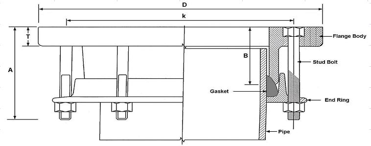
14) On completion of the bolt tightening, the radial gap between the pipe and inside diameter of the gland ring should be even
all around the fitting. Some evidence of rubber extruding between the pipe and gland ring might be evident.
Notes:
• These flange adaptors will not provide end restraint, this must be provided by other means.
• External Loading action on the fittings might have serious effects upon its performance such as weights of pipelines, spool
pieces, back fill etc... All pipes should be supported independently on each side of the fitting.
• It is advisable to replace all stainless steel fasteners in the event of having to reposition the fitting.
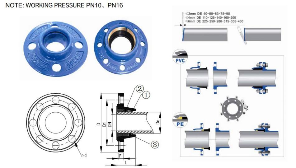
The front end of the rubber ring to form a certain angle, the profile looks like a right triangle. As shown below:
Application
This product is used for the flange adapter, the installation of the inner diameter of the need to close the pipe wall, together with the flange into the adapter slot, rely on tightening screws, the role of pressure on the apron, has reached the effect of sealing leakage.
Taking into account the use of flange adapter requirements, the flange rubber ring physical mechanics requirements, health applications are more stringent requirements.
RSL flange adapter rubber ring has passed the professional standard BS EN681-1 physical performance test, and the EU recognized WRAS certification. Choose our apron, will be able to meet your critical requirements. Come today to contact us!
Flange adapter Rubber ring
What Is a Flange Adapter?
Flange adapters are an extensive family of flange joint accessories that allow the execution of joints between dissimilar flange types or flanged and non-flanged equipment. The significant flexibility gained by using these devices becomes apparent when the enormous range of common flange types in general use is considered. In fact, most manufacturers of flanges or flanged equipment produce their own lines of flange adapter accessories, allowing their products to be integrated into other systems with ease. Although these adapters are themselves represented by a vast array of different types, they fall into two main categories. The first are flange-to-flange types, with the second being those used to join flanged and non-flanged equipment.
Flanges are little more than flat discs or shoulders integral to or loose fitting on the relevant part or pipe. The flange disc is fitted with a number of holes around its periphery through which locking bolts are passed. To join two similarly flanged pieces of equipment, the two halves are brought together, locking bolts are passed through the holes in both flange discs and tensioned. This pulls the two flanges hard up against one another, effectively joining the two pieces of equipment.
The flange adapter is used where the two pieces of equipment do not have similar flange types or only one-half is flanged. These adapters fall into two broad categories, namely those used on dissimilar flange pairs and those used in situations where a non-flanged part is joined to a flanged part. Flange-to-flange adapters are usually represented by those adapters designed for dissimilarly-sized flanges and those used to join flanges of the same size with differing hole arrangements.
Joints featuring flanges of different sizes may easily be made using a flange adapter featuring one of each of the two flange sizes joined by a short reducer section. These adapters are simply arranged so the relevant flange sizes are matched between the parts and the adapter, and tensioned in the normal fashion. Adapters used to join flanges with differing hole patterns are even simpler and typically consist of a single disc drill halfway through on either side with the two different hole patterns. The holes in the adapter are tapped with a standard screw thread so that, when slipped between the two dissimilar flanges, bolts can be used to tension each of them up against the adapter. In general, this type of adapter will be supplied with a set of the correct bolts.
Flanged to non-flanged joints require a special type of flange adapter that generally has a flange on one end and a secondary locking mechanism suitable for the relevant equipment on the other. For instance, a flange adapter designed to join an non-flanged hose to a flange-equipped pipe will have a suitably-sized flange on one end and a compression or half-shell hose clamp on the other. The flanged end is bolted to the secondary device's flange in the normal way and the non-flanged hose securely attached with the hose clamp.
Flange adapters are used to join a flanged part to the spigot end of a pipe or tube. They are used to connect networks composed of different materials. They can also be specially designed for one material. In this case, they are offered in anchoring or non-anchoring versions. With the self-anchoring (locking) products, concrete anchor blocks are unnecessary.
The flange adaptor is the most basic type of dismantling joint. On one side, it has a flange connection in accordance with the required flange standard, on the other an insertion socket for the pipe. A variety of standard pipe types can be connected.
flange adaptors are available for a variety of pipe types. The anti-torque bolts also make the flange adaptor suitable for a fast “one-man installation”.
There are two types of Flange Adapters
1) Weldable Type Flange Adapter
2) Flange Type Flange Adapter
Features:
• ±4° angular deflection
• Drinking water approved EPDM gasket
• The design with external bolts prevents corrosion between sleeve and bolts
• The bolts of stainless steel A2 and the nuts of acid-resistant stainless steel A4 are anti-friction coated to offer
easy tightening and to prevent galling
• The bolt ends are protected with plastic caps
• The moulded ribs in the gasket absorb minor imperfections in the pipe
• Ductile iron with epoxy coating according to DIN 30677-2 and AVK guidelines
Installation
1) All of the series 600 mechanical fittings are supplied as an assembled unit ready for use, dismantling of the parts is
unnecessary.
2) Examine fitting before assembling to ensure that no damage has occurred during transit.
3) Check that the sealing range indicated on the label of the fitting is compatible with the actual pipe diameter.
4) When assembling Supa Flange Adaptors, check that the Nom Flange size and Pressure ratings are compatible with the valve.
5) Check that the sealing element supplied is suitable for the medium conveyed in the main.
6) Examine the pipe end to which the fitting is to be assembled, ensuring that it is round and square and free from dents, bulges
and score marks.
7) When assembling to a steel pipe which has longitudinal seam welds, the weld seam must be removed by grinding. Care
should be taken to ensure that the pipe surface profile is maintained.
8) The pipe end must be cleaned by wire brushing, to remove all rust, scale or debris.
9) Lubricate inside diameter of sealing elements with a WRAS approved lubricant.
10) Position pipe end to be coupled, checking that it is level and concentric with the bore of the mating flange, and that the
correct setting gap is maintained.
11) RECOMMENDED GAP SETTINGS
DN 40 to DN200 Maximum setting gap = 20mm
DN250 to DN400 Maximum setting gap = 37mm
12) Bolt tightening can now commence, using a torque spanner capable of 50/55 Nm.
13) Tighten diametrically opposed bolts as indicated on label, to ensure that the sealing element is loaded evenly. It is essential
that all bolts are torqued evenly as indicated on the label (50/55 Nm).
14) On completion of the bolt tightening, the radial gap between the pipe and inside diameter of the gland ring should be even
all around the fitting. Some evidence of rubber extruding between the pipe and gland ring might be evident.
Notes:
• These flange adaptors will not provide end restraint, this must be provided by other means.
• External Loading action on the fittings might have serious effects upon its performance such as weights of pipelines, spool
pieces, back fill etc... All pipes should be supported independently on each side of the fitting.
• It is advisable to replace all stainless steel fasteners in the event of having to reposition the fitting.
Application
| performance | unit | Hardness level requirements | |||||
| 40 | 50 | 60 | 70 | 80 | 90 | ||
| Tolerance of nominal hardness | IRHD | ±5 | ±5 | ±5 | ±5 | ±5 | ±5 |
| Tensile strength, minimum | Mpa | 9 | 9 | 9 | 9 | 9 | 9 |
| Pull elongation, minimum | % | 400 | 375 | 300 | 200 | 125 | 100 |
| Compression permanent deformation,maximum 20℃,72h 70℃,24h -10℃,72h |
% % % |
12 20 40 |
12 20 40 |
12 20 50 |
15 20 50 |
15 20 60 |
15 20 60 |
| Ageing,70℃,7d Hardness change, Maximum Tensile strength change rate, maximum Pull the elongation rate of change, the largest |
IRHD % % |
-5~+8 -20 -30~+10 |
-5~+8 -20 -30~+10 |
-5~+8 -20 -30~+10 |
-5~+8 -20 -30~+10 |
-5~+8 -20 -40~+10 |
-5~+8 -20 -40~+10 |
| Stress relaxation, maximum 23℃,7d 23℃,100d |
% % |
13 19 |
14 20 |
15 22 |
16 23 |
17 25 |
18 26 |
| The volume change in the water, the largest 73℃,7d |
% | -1~+8 |
-1~+8 | -1~+8 | -1~+8 | -1~+8 | -1~+8 |
| Resistant to ozone | - | In the absence of amplification under the conditions of observation, no cracks | |||||
| Compression permanent deformation, maximum -25℃,72h |
% | 60 | 60 | 60 | 70 | 70 | 70 |
| Hardness change, maximum -25℃,168h |
IRHD | +18 | +18 | +18 | - | - | - |
| NO. | NAME | SIZE | PRICE (RMB) | PRICE (USD) | |||
| D | M | H1 | H2 | ||||
| 1 | DN600 | 616 | 18.5 | 35 | 11 | 63.80 | 9.20 |
| 2 | DN500 | 528 | 18.0 | 35 | 11 | 53.90 | 7.80 |
| 3 | DN450 | 466 | 16.0 | 34 | 11 | 45.10 | 6.50 |
| 4 | DN400 | 416 | 15.0 | 33 | 11 | 35.20 | 5.10 |
| 5 | DN350 | 375 | 15.0 | 33 | 11 | 28.10 | 4.10 |
| 6 | DN300 | 316 | 15.0 | 33 | 11 | 22.60 | 3.30 |
| 7 | DN250 | 265 | 14.0 | 32 | 11 | 17.80 | 2.60 |
| 8 | DN200 | 215 | 13.0 | 31 | 11 | 13.90 | 2.00 |
| 9 | DN150 | 165 | 13.0 | 30 | 10 | 8.70 | 1.30 |
| 10 | DN100 | 114 | 12.5 | 30 | 10 | 6.70 | 1.00 |
| 11 | DN80 | 95 | 12.5 | 29 | 10 | 5.30 | 0.80 |
| 12 | 24″ | 667 | 18.5 | 35 | 12 | 63.80 | 9.20 |
| 13 | 18″ | 507 | 17.0 | 34 | 11 | 45.10 | 6.50 |
| 14 | 16″ | 458 | 16.0 | 34 | 11 | 35.20 | 5.10 |
| 15 | 12″ | 345 | 16.0 | 33 | 11 | 22.60 | 3.30 |
| 16 | 10″ | 282 | 14.0 | 33 | 11 | 17.80 | 2.60 |
| 17 | 8″ | 228 | 15.0 | 32 | 11 | 13.90 | 2.00 |
| 18 | 6″ | 174 | 13.0 | 30 | 10 | 8.70 | 1.30 |
| 19 | 4″ | 121 | 13.0 | 33 | 9 | 6.70 | 1.00 |
| 20 | 3″ | 96 | 13.0 | 28 | 9 | 5.30 | 0.80 |
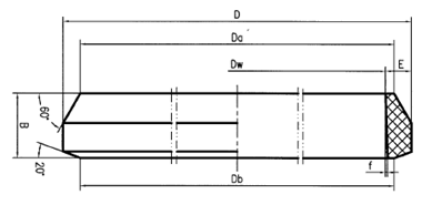
| NAME | Dw | D | Da | Db | f | B*E | PRICE (RMB) | PRICE (USD) |
| DN700 | 711 | 751 | 721 | 720 | 1.5 | 40*20 | 156.20 | 22.60 |
| DN800 | 813 | 853 | 823 | 822 | 1.5 | 40*20 | 190.30 | 27.50 |
| DN900 | 914 | 954 | 924 | 923 | 1.5 | 40*20 | 227.70 | 33.00 |
| DN1000 | 1016 | 1056 | 1026 | 1025 | 1.5 | 40*20 | 266.20 | 38.50 |
| DN1200 | 1219 | 1259 | 1229 | 1228 | 1.5 | 40*20 | 310.20 | 44.90 |
| DN1400 | 1422 | 1462 | 1432 | 1431 | 1.5 | 40*20 | 367.40 | 53.20 |


